|
|
 |
|
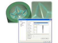
The rest finishing is aimed at semi-finishing and finishing internal corners. The area machined is limited by a reference cutter, defined by the user. A ball nose cutter is used, steep areas are separated from shallow areas, like all other types of passes the cutter and holder are protected from gouging. Spiral like linking allows for the milling direction to be maintained in the shallow areas. In the steep areas, the cutter is kept in the part as much as possible, reducing any air cutting. |
 |
|
Corner offset machining is similar to constant offset machining. However with this technique, rather than starting from an outside boundary and working in towards the centre of the part. A set of pencil milling passes are created on the features of the part, then a toolpath calculated over the whole part from those features. The toolpath maintains a constant and equidistant surface finish over the whole part. The resultant surface finish in the corners can be significantly better than 3D constant offset machining depending on the shape of the part, as the toolpath follows the 3D form and features and can be used in conjunction with cutter contact angles. |
 |
|
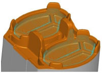
Boundary machining, machines along an open or closed boundary profile. A negative machining thickness can be used to machine at constant depth below the surface being machined and can be used in conjunction with cutter contact angles.
Boundary machining can be used for the machining of mould tool runner detail, or applied to engraving text which can be generated using the Windows True Type fonts within the NCG CAM system. The fonts available will depend on the users Windows operating system. |
 |
|
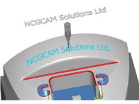
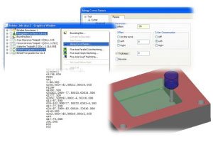
Machining along a curve is just as it says -it is the curve that is machined not the surface data. This will allow a toolpath to be generated below the surfaces if needed.
Curves can be extracted from the model in some cases, if extracted from the model the curve may be 3D and will be respected as 3D when machined. Curves may also be created from boundaries with a convert to curve function, there is also a convert curve to boundary function.
 Curves that are made from a boundary will be 2D. As a boundary there are editing functions like roll, open/break, close, offset, union, intersection, subtraction and convex hull. Curves that are made from a boundary will be 2D. As a boundary there are editing functions like roll, open/break, close, offset, union, intersection, subtraction and convex hull.
Curves can be joined to get a continuous profile –often in a model it will be several bits of curve that are wanted; joining the bits will reduce the number of retract moves.
The along curve machining supports 2D cutter compensation (G41 & G42 or cutter left/cutter right). This enables 2D profiles to be sized on the machine tool; the toolpath has arc fitting for optimised output. Cutter compensation is only available on a 2D curve.
|
|
|
|
|
|

